How to Size a Distribution Transformer: kVA, Voltage & Load Explained
Selecting the right distribution transformer is one of the most consequential decisions on any power project. An undersized unit runs hot, ages prematurely and limits future expansion; an oversized unit ties up capital, occupies valuable floor space and operates inefficiently at light load. Sizing is not guesswork — it follows a clear sequence: establish the connected load, convert it to apparent power, confirm the voltage and connection requirements, then add margin for growth and site conditions. With more than three decades of manufacturing experience supplying transformers and switchgear to industrial and utility buyers worldwide, we see the same sizing questions again and again. This guide walks through the process in practical terms.
Step 1: Determine the Real Load, Not the Nameplate Sum
Start by listing every load the transformer will serve — motors, lighting, HVAC, process equipment, chargers, IT loads. Simply adding all nameplate ratings almost always produces an inflated figure, because loads rarely peak simultaneously. Two adjustments matter:
- Demand factor — the share of connected load actually operating at any moment.
- Diversity — peaks of different load groups occurring at different times.
Where reliable metered data exists on an existing facility, use it. Where it does not, apply the demand factors given in the governing installation code for your jurisdiction rather than an informal rule of thumb. The result is a realistic maximum demand in kW.
Step 2: Convert kW to kVA
Transformers are rated in kVA (apparent power), not kW (real power). The conversion depends on the power factor of the load:
kVA = kW ÷ power factor
A facility dominated by induction motors will have a noticeably lower power factor than one dominated by resistive or corrected loads, so the same kW figure can call for a meaningfully larger transformer. If power-factor correction equipment is planned, size for the corrected condition — but confirm the correction will actually be in service at peak.
For a three-phase system, the relationship between line values is:
kVA = (√3 × line voltage × line current) ÷ 1000
Step 3: Confirm Voltage, Frequency and Connection
Capacity is only half the specification. Before a unit can be built, the following must be fixed:
| Parameter | What to confirm |
|---|---|
| Primary voltage | Utility or upstream distribution voltage at the point of connection |
| Secondary voltage | Utilisation voltage required by the downstream equipment |
| Frequency | 50 Hz or 60 Hz — a transformer built for one is not interchangeable with the other |
| Phases | Single-phase or three-phase |
| Vector group / connection | Delta–wye, wye–wye, etc., and the required phase displacement |
| Tap range | Off-circuit or on-load taps to accommodate supply voltage variation |
| Impedance | Affects voltage regulation and downstream short-circuit levels |
Impedance deserves particular attention. A lower impedance improves voltage regulation but raises the fault current the downstream switchgear must interrupt; the transformer and the protective devices should be specified together rather than in isolation.
Step 4: Add Margin — Growth, Duty and Environment
Once the calculated kVA is known, it is rounded up to the nearest standard rating. Beyond that, several factors justify additional headroom:
- Future expansion. Adding capacity later usually costs far more than specifying it now. A modest allowance for planned growth is normal practice.
- Load character. Frequent motor starting, welding, or other cyclic loads impose peaks well above the average demand.
- Harmonics. Variable-frequency drives, rectifiers and switch-mode supplies inject harmonic currents that cause extra heating; non-linear-heavy installations may require a K-rated or otherwise de-rated design.
- Ambient conditions. High ambient temperature, high altitude, and enclosed or poorly ventilated rooms all reduce the capacity a given unit can deliver continuously. State the site conditions clearly at enquiry stage so the design can account for them.
Equally, avoid excessive oversizing. A transformer loaded far below its rating still incurs no-load (core) losses around the clock, so a much larger unit than necessary costs money every hour of its life.
Step 5: Match the Sizing to the Right Transformer Type
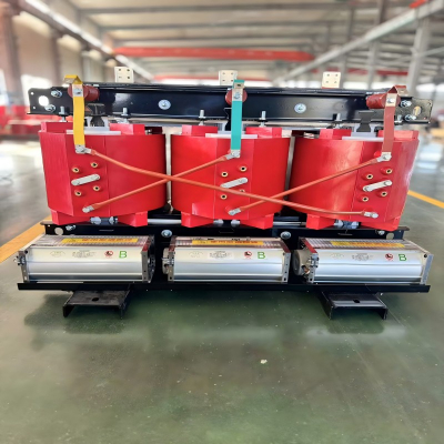
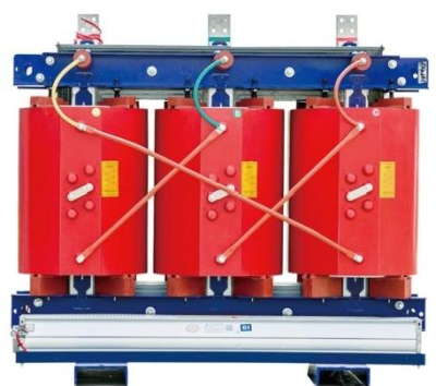
The final step is choosing a construction suited to the installation. Dry-type transformers are widely used indoors and in locations where fire load and fluid containment are concerns. Oil-immersed transformers are commonly selected for outdoor and higher-capacity duty, where their cooling performance is advantageous. Where a complete outdoor distribution point is needed, a box-type (compact) substation integrates the transformer with incoming and outgoing switchgear in one enclosure.
Getting the Specification Right the First Time
Accurate sizing depends on accurate inputs. When you request a quotation, supplying maximum demand, power factor, primary and secondary voltage, frequency, phases, expected load growth, installation environment and any applicable standard will produce a far more precise proposal than a bare kVA figure. Our engineering team reviews these details on every enquiry and will flag anything that looks inconsistent before manufacture begins.
Need help sizing a transformer for your project? Contact our engineering team with your load data and site conditions, and we will prepare a tailored recommendation and quotation.